Optimizing SMD LED and Optopipe® Light Pipe Integration
Comparing AlInGaP, GaP, and InGaN LED Technologies
Things to Know - SMT vs THT
Choosing LED Viewing Angles

Topics
As the transportation industry continues to evolve through electrification, autonomy, and connectivity, LED indicators have become essential components in vehicle and system design. These small but powerful devices provide critical visual feedback for operators, passengers, and service technicians. They support safety, communication, and reliability in demanding environments across all modes of transport.
The Expanding Role of LED Indicators
Vehicles today are more complex and electronic than ever before. LED indicators play an important role in keeping those systems transparent and manageable.
They offer:
• Instant illumination for real-time feedback and faster decision-making
• Long operating life, often exceeding 100,000 hours, reducing maintenance and downtime
• Resistance to vibration, shock, moisture, and extreme temperatures, which is essential in rugged and mobile environments
• Low energy consumption, which supports efficiency in power-constrained systems like electric vehicles
Applications Across Vehicle Types
In electric vehicles, LED indicators support critical feedback on systems such as battery charging, thermal management, and motor operation. Their energy efficiency directly contributes to extended range and reduced drain on the vehicle’s electrical system.
In fire trucks, bucket trucks, and other specialized utility vehicles, indicators are used to show operator status such as boom position, hydraulic system activity, or warning signals when interlocks are not engaged. These are often panel-mount indicators installed in control consoles, engineered to perform reliably in harsh outdoor conditions.
Connected and Autonomous Systems
The next generation of transportation requires smarter indicators. In autonomous vehicles, infrared LED technology is used in driver monitoring systems to assess alertness. Indicators are also part of systems that show operational status or alerts directly to pedestrians and other road users, improving situational awareness and trust.
Connected vehicles, which communicate with infrastructure and other vehicles, rely on LED indicators for both internal and external messaging. These indicators can provide immediate visual feedback on system status, safety alerts, or V2X communication signals.
Transit and Rail Environments
Rail and transit systems use LED indicators to enhance safety and improve user experience. They are used in operator dashboards, platform systems, and emergency signaling. In these settings, visibility under bright sunlight, customizable signal colors, and robust construction are key design factors.
Engineering for Harsh Conditions
Designers selecting indicators for transportation applications should look for features like:
• Sealing and protection ratings such as IP67 or NEMA 4X for outdoor or wet environments
• Voltage and current compatibility with vehicle or trackside systems
• Mounting flexibility to fit tight or specialized spaces, including options for board-mounted and panel-mounted designs
• Clear, color-accurate illumination that can be seen in high-vibration and high-glare conditions
Built for What Moves the World
From EVs and mining trucks to light rail cars and airport shuttles, LED indicators are vital to vehicle safety, efficiency, and usability. As transportation systems become smarter and more electrified, reliable indication becomes even more critical.
LED indicators are not just lights. They are communication tools, status reporters, and safety enablers. And when they are engineered for durability and clarity, they help keep vehicles moving and people safe.
A 3-Step Guide for Optimal Performance

Optimizing the use of SMD LEDs with light pipes requires careful consideration. The relationship between application requirements and the choice of a suitable light pipe is crucial. Here's a short, 3-step, guide for optimal light pipe performance:
1. Aligning Design Layout:
To determine the appropriate light pipe style, consider the alignment of the design layout. This will depend on the intended use of the light pipe: either for Direct View or for Backlighting an overlay window on the front panel. Each choice has implications for the lens style and output surface.

Light pipe charcteristics: Pipe shape, lens type, and output surface.
Light pipes designed for Direct View may extend from the front panel and feature a convex or domed lens. They can either be flush with the panel or slightly recessed. These types of light pipes typically have a textured output surface to diffuse the light output.

Animation of flush mounted, vertical light pipe for applications with overlays.
On the other hand, light pipes used to illuminate panels with overlays are usually flush with the panel. The choice of a clear or textured output surface depends on whether a clear and bright indication or a diffused look is desired.

Three basic rigid light pipe types: right-angle PCB mount, vertical panel mount, and vertical PCB mount.
When considering the placement of the circuit board in relation to the panel, it is important to choose the appropriate light pipe configuration. For PCBs mounted at a 90° angle from the panel, a right-angle light pipe with a top-mounted/top-view SMD LED is recommended. Alternatively, using a vertical (straight) light pipe with a right-angle LED can achieve the same results.
For circuit boards that are installed parallel to the panel, the typical pairing is a vertical light pipe with a top-mounted/top-view SMD LED.
The method of securing the light pipe will also impact the choice of light pipe for your application. Board-mount (snap-in) and panel-mount (press-fit) options are available for both vertical and right-angle light pipes. The decision often depends on the available board space and assembly preference for the specific application.
2. Matching LED and Light Pipe:
For optimal light capture, it is crucial to match the entrance of the light pipe to the LED effectively. One recommendation is to choose an SMD LED with a reflector cup or a lens featuring a narrow viewing angle. Position it close to the input surface of the light pipe, within the tolerances of the light pipes and LED PCB assembly. This ensures consistent and reliable indication.
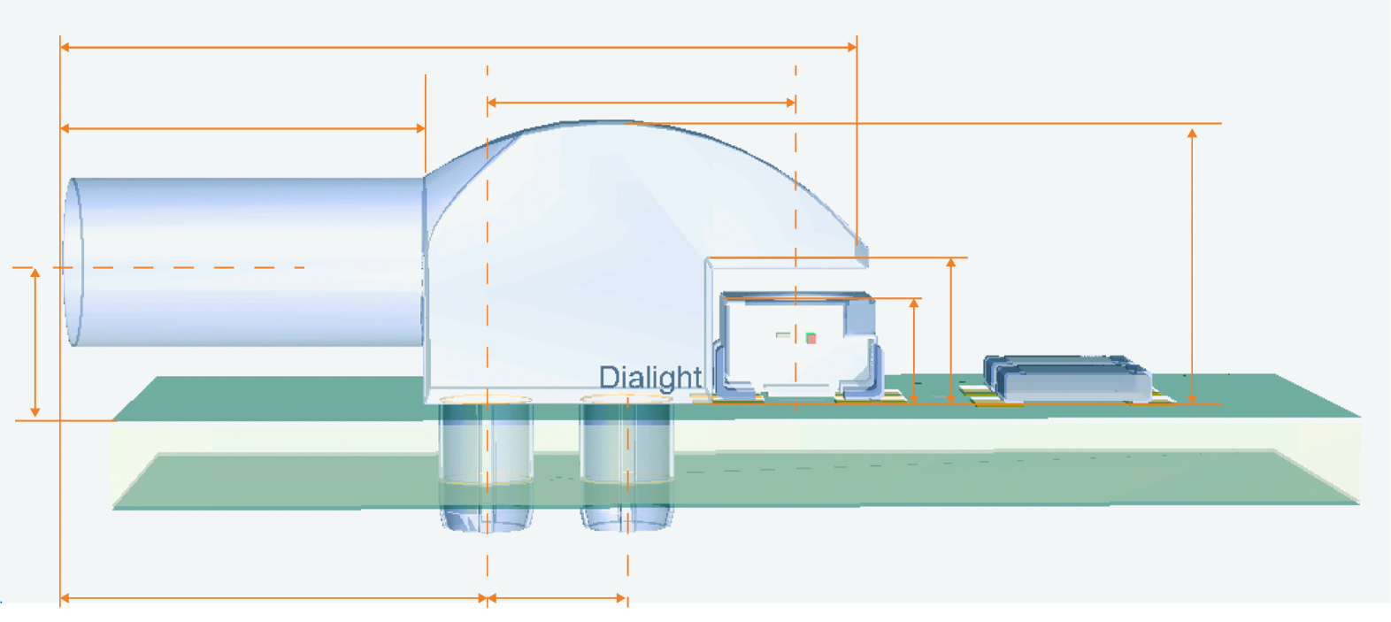
Example of crucial dimensions of the light pipe and LED PCB assembly.
Consider your desired visual output for the light pipe and the applicable current (ma). It is advisable to select SMD LEDs that are bright enough, allowing you to adjust the intensity externally. By using current limiting resistors and adjusting the drive current to the LED, you can achieve the desired intensity level.
3. Preventing Light Bleed: Light bleed is of particular concern when using multi-position light pipes or arrays with minimal spacing between them. To prevent light bleed, which can lead to problems like false readings and color mixing, it is important to use light pipes with light shields. Light shields effectively control light bleed, eliminate the potential for optical cross-talk, and help maximize the light pipe output.
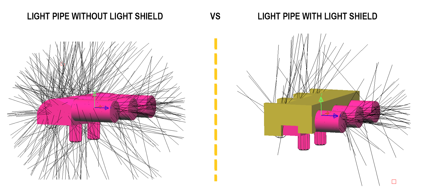
Light scatter comparison of light pipe array with and without light shield.
To ensure optimal indication performance and to navigate the complexities of utilizing SMD LEDs with light pipes, it is recommended to seek guidance from LED indication experts like Dialight. Their expertise and assistance can greatly aid in selecting the right LEDs and light pipes for your specific project requirements. By consulting with them, you can achieve the best possible outcome for your application.
A Bright Spectrum of Choices
In the context of LED (Light Emitting Diode) technology, there are a variety of materials and technologies that are suitable for different applications requirements. Some of the popular options are AlInGaP (Aluminum Indium Gallium Phosphide), GaP (Gallium Phosphide), and InGaN (Indium Gallium Nitride) LEDs. Each of these materials offers unique characteristics and uses. In order to make informed choices for your next LED indicator or display project we will look at how AlInGaP, GaP, and InGaN LED technologies compare.
Material Composition
AlInGaP LEDs: These LEDs consist of Aluminum (Al), Indium (In), Gallium (Ga), and Phosphorus (P). This composition allows them to emit colors ranging from red to yellow.
GaP LEDs: GaP LEDs are primarily made from Gallium (Ga) and Phosphorus (P), mainly used for green and yellow-green LEDs.
InGaN LEDs: InGaN LEDs contain Indium (In), Gallium (Ga), and Nitrogen (N), offering a wide range of colors, including blue, green, and white.
Wavelength Range
AlInGaP LEDs: Boasting a broad wavelength range, AlInGaP LEDs can produce colors like red, orange, and yellow.
AllnGap Orange: 600-615nm
AllnGap Yellow / Amber: 580-595nm
AllnGap Yellow-Green: 565-575nm
GaP LEDs: GaP LEDs are limited to green and yellow-green light emissions.
GaP Red: 700nm
GaP Green: 560-572nm
InGaN LEDs: InGaN LEDs allow for an extensive spectrum of colors. Blue and green are the standard colors produced with InGaN technology. However, with the application of phosphor to the LED die surfaces, a process referred to a Phosphor Conversion (PC), it enables a broad spectrum of color production including white light.
InGaN Green 515-535nm
InGaN Blue 460-475nm
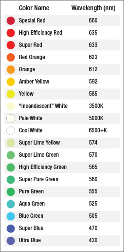
Reference chart for LED colors and wavelengths.
Efficiency
AlInGaP LEDs: Known for their high internal quantum efficiencies, AlInGaP LEDs efficiently convert electrical energy into light.
GaP LEDs: While still efficient, GaP LEDs are not as energy-efficient as AlInGaP or InGaN LEDs.
InGaN LEDs: InGaN LEDs are highly efficient, making them suitable for various high-brightness applications.
Brightness
AlInGaP LEDs: AlInGaP LEDs can be quite bright, making them suitable for applications requiring high luminosity.
GaP LEDs: GaP LEDs offer moderate brightness and are suitable for applications where brightness requirements are not as high.
InGaN LEDs: InGaN LEDs are known for their high brightness levels, especially in blue and green variants.
Applications
AlInGaP LEDs: These LEDs are commonly found in traffic signals, automotive taillights, and indicators requiring red, orange, or yellow light. They are also used in certain displays and signage.
GaP LEDs: GaP LEDs find their niche in green indicator lights, displays, instrument panels, and some consumer electronics.
InGaN LEDs: InGaN LEDs are versatile and used in a wide range of applications, including traffic lights, smartphone screens, backlighting, and general lighting.
Cost
AlInGaP LEDs: Due to their complex material composition, AlInGaP LEDs are typically more expensive to manufacture.
GaP LEDs: GaP LEDs are often cost-effective, making them a budget-friendly choice for various applications.
InGaN LEDs: InGaN LEDs, while efficient and versatile, can be costlier than GaP LEDs but offer superior performance.
Performance
AlInGaP LEDs: AlInGaP LEDs, due to their construction, generally offer lower forward voltages, less than 2.8 volts, than InGaN LEDs making them ideal for low voltage battery and handhelds application. Additionally they offer a better longer term light output stability vs some older technology LEDs in high humidity environments and outdoor applications. In applications with broad operating temperatures, the design must also consider the impact of the operating temperature on the LED intensity. The typical AlInGAp Red LEDs may lose as much as 30% of the room temperature output at elevated temperatures and amber as much as 50% of the room temperature intensity may be lost at elevated temperatures
GaP LEDs: Like AlInGaP LEDs GaP LEDs perform very similar to AlInGaP, however due to their lower intensity outputs that are best suited for indoor applications
InGaN LEDs: InGaN LEDs typically have a forward voltage greater than 3.0 volts, However due to the superior light output performance and be operated at lower currents improving their overall power consumption. With a typical intensity reduction of less than 10% at elevated temperatures, InGaN LEDs provide a very stable light output over a broad operating temperature range.
Understanding the differences among these LED technologies helps designers and manufacturers select LEDs that produce the desired brightness in the required spectrum of colors for their visual indication needs.
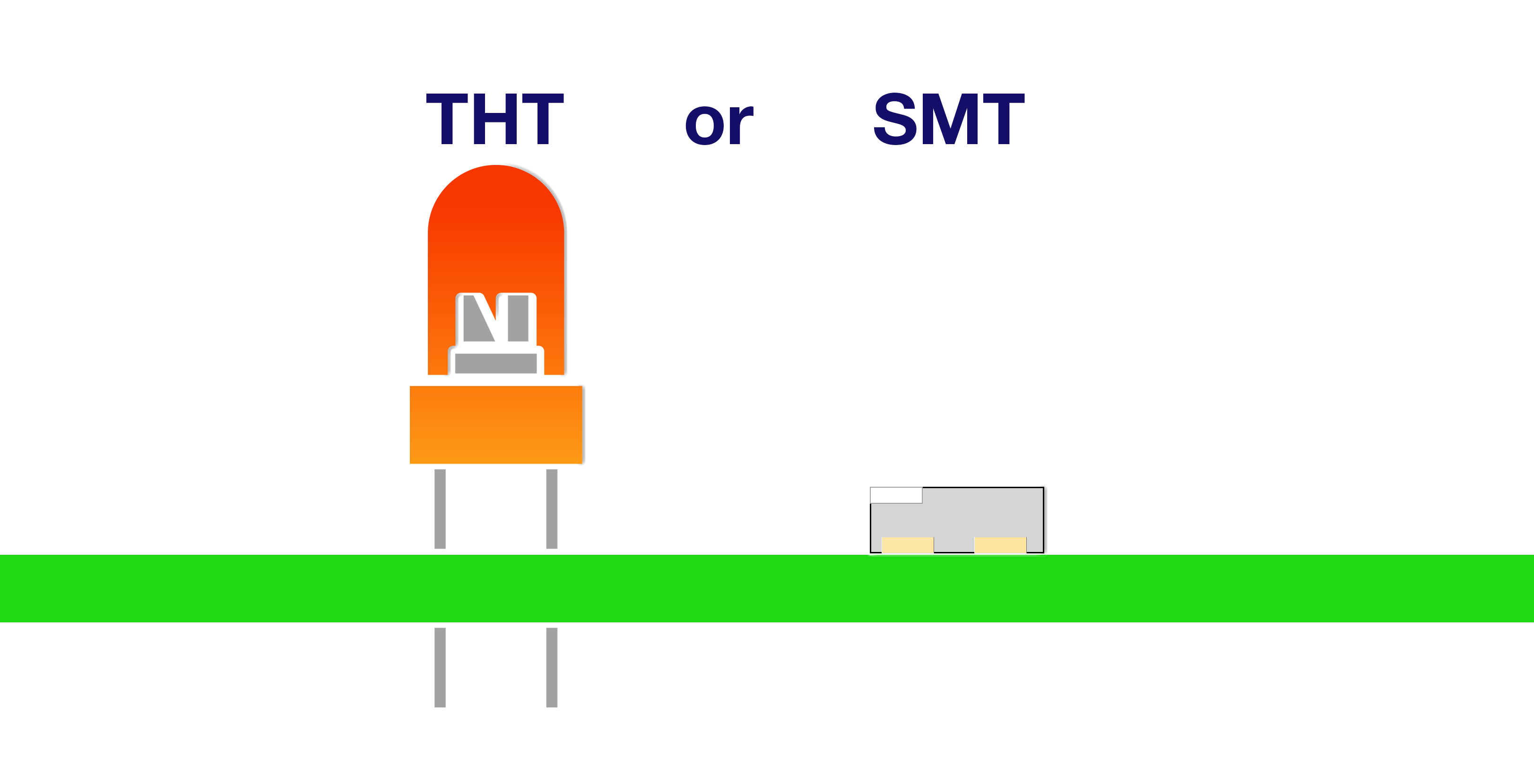
When incorporating LED indicators in printed circuit board (PCB) applications, design engineers must decide between surface mount technology (SMT) LEDs and through-hole technology (THT) LEDs. Here are some key considerations when making this choice:
1. SMT LEDs take up less space on the board since they do not require drill holes. This enables tighter packing densities and a smaller overall circuit size.
2. Housed THT LEDs allow for ganged arrays which are not offered in SMT.
3. SMT LEDs allow for automated assembly and faster production. The LEDs are simply placed and soldered by pick-and-place machines.
4. THT LEDs are installed manually by inserting leads through holes and soldering. This takes more time and labor.
5. SMT LEDs generally have better thermal management as the flat bottom surface adheres closely to the PCB for heat conduction.
6. THT LEDs can withstand more mechanical stress and vibration as the leads provide support. SMT LEDs rely solely on the solder joint.
7. SMT LEDs are recommended for high-density designs with space limitations. THT LEDs allow more flexibility in positioning.
8. THT LEDs are easier to replace or upgrade selectively if needed. SMT LEDs require specialized tools for desoldering.
9. Housed THT LEDs allow for multi-level configurations 2 to 4 high without sacrificing space on the PCB.
10. The viewing angle and brightness specifications should be evaluated to ensure the chosen technology meets visibility needs. THT LEDs provide direct viewing of the LED, allowing for higher intensity and in some cases wider viewing angles.
11. Regulations may dictate the use of THT LEDs in certain applications like high-reliability aerospace systems.
⬜⬜⬜⬜ ◻◻◻◻
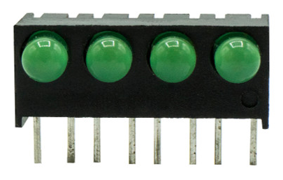
4 wide through hole (THT) circuit board indicator array. Dialight 551-0207-004F


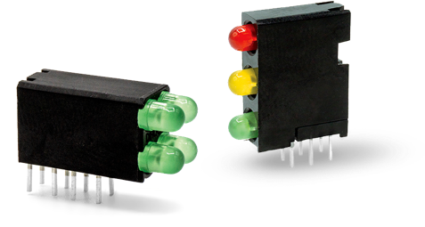
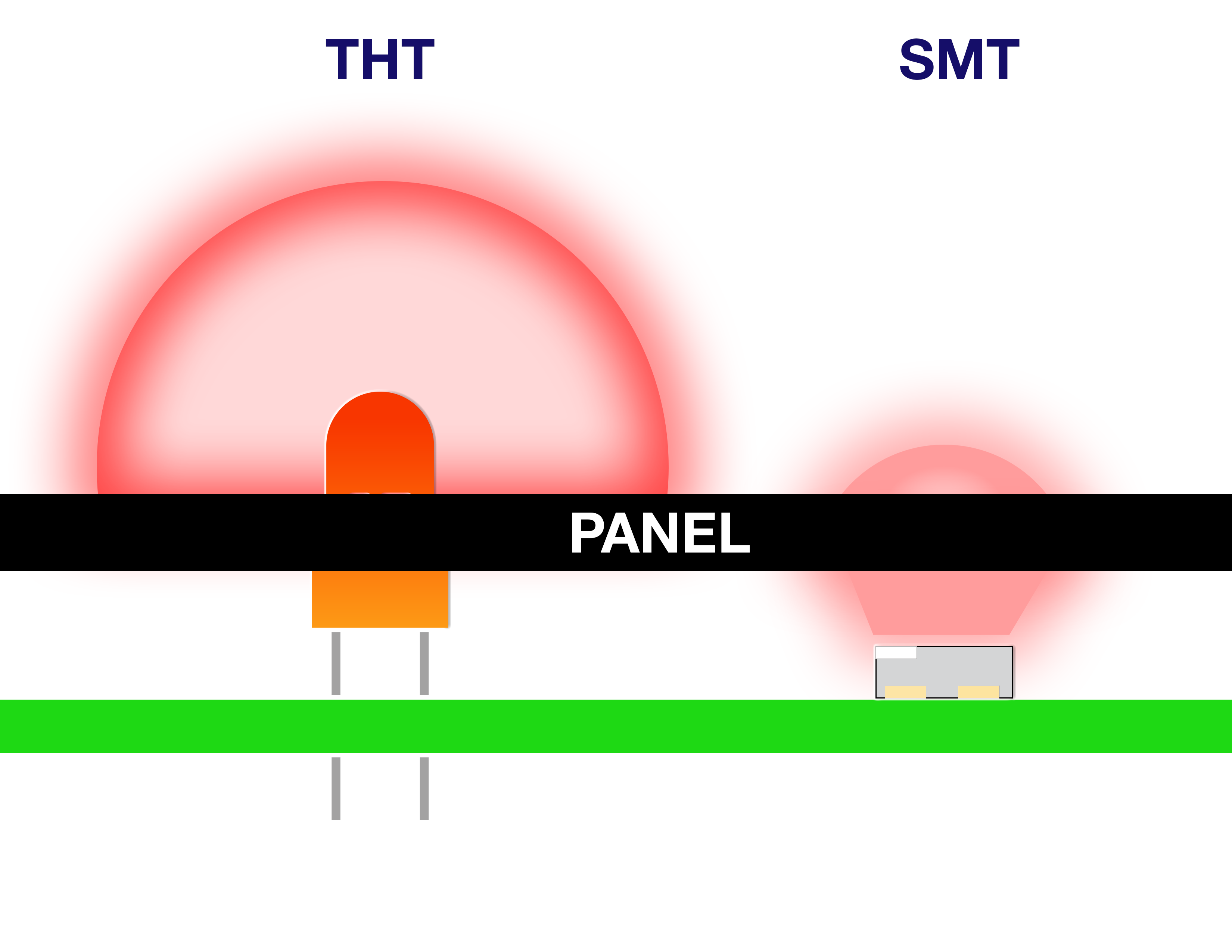
This chart visually captures the main trade-offs between the two technologies when designing with LED circuit board indicators.

SMT LEDs are usually preferred for small, compact indicator designs thanks to their miniaturized footprint. But THT LEDs have advantages in resilience, serviceability, and flexibility. Consider all factors including long-term maintainability and inspection requirements when selecting the best LED indicator technology for your application design.
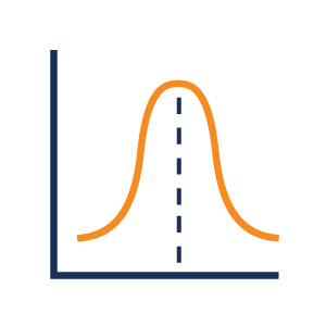
When it comes to selecting LEDs for circuit board indicators, the viewing angle plays a crucial role in determining visibility and brightness. Here are some important considerations to keep in mind:
1. Opt for a narrower degree viewing angle when the LEDs are placed on the board for backlighting a panel or when direct visibility is required. This will maximize straight-on brightness as the concentrated beam enhances visibility head-on.
2. For LEDs placed on the edges or sides of the boards with a need to be viewed from a variety of angles to the system i.e. diagnostic indicators, a slightly wider degree angle is recommended. This will spread the light and ensure better visibility from oblique angles.
3. Keep in mind that wider degree angles may appear dimmer from the front, as the light is distributed across a broader field of view.
Take into account the LED's mounting orientation and lens design, as these factors can impact the effective viewing angle.
4. Consider the ambient lighting conditions, as LEDs with narrow beams are more resistant to washout from bright surroundings.
5. Don't forget to consider factors like directivity, beam pattern, regulations, and application requirements when selecting the ideal viewing angle.
6. Experiment with different LED viewing angles to determine the optimal visibility for each board's layout and intended viewing direction.
7. Specifications provided will indicate the viewing angle and intensity, which will help narrow down the selection.
Narrow Viewing Angle:
Range between 10 to 25 degrees
Medium Viewing Angle:
Range between 30 to 70 degrees
Wide Viewing Angle:
Range between 120 to 140 degrees
In summary, the LED viewing angle plays a crucial role in determining the visibility and brightness of circuit board indicators. If LEDs have the same total light output but different viewing angles, the way they appear when viewed directly will be influenced by the viewing angle. Narrow-degree angles are ideal for optimizing straight-on visibility and backlighting, while wider-degree angles allow for visibility from more oblique angles if needed.